Logical circuit design
Inquiry Sitemap Link Tips
Synchronization

Combination sample RTL of different termination timing

Routing
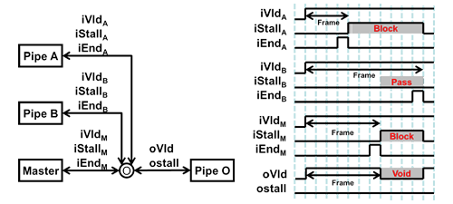
  • By combination control pipeline 0 by termination flag end.
  • When all pipelines output end then terminate the frame
  • Manage whether the end is early or late from the standard for each pipeline.
  • It is OK to control the condition by measuring the number of each end, (number of FF maybe saved but when number of pipeline is large then logical stages can get very large.)
  • Omit data coding
Latency(CLK)0
    
    module combine(iVld, iStall, iEnd, oVld, oStall, reset, clk);
            parameter       N       = 4;

            parameter       IDLE    = 2'h0,
                            PASS    = 2'h2, // Late End
                            BLOCK   = 2'h3; // Early End
    
            input   [N-1:0] iVld;
            output  [N-1:0] iStall;
            input   [N-1:0] iEnd;
            output          oVld;
            input           oStall;
            input           reset;
            input           clk;
    
            reg     [N-1:0] cnd[0:N-1];     // Pipeline Condition
            reg     [N-1:0] cndD[0:N-1];    // Number0 is useless
            reg     [N-1:0] iDummyVld;      // Condition = EARLY
            reg     [N-1:0] iDummyStall;    // Condition = LATE
            reg     [N-1:0] iDummyVldD;
            reg     [N-1:0] iDummyStallD;
            wire    [N-1:0] iAlloc  = iVld & ~iStall & iEnd;
            wire            iDone   = &(iAlloc | iDummyStall);
    
            wire            nasc    = &(iVld | iDummyVld) & ~|oStall;
    
            integer         i;
    
            always @(posedge clk)
                    if (reset) for (i=0; i<N; i=i+1)
                            cnd[i]  <= #1 IDLE;
                    else for (i=0; i<N; i=i+1)
                            cnd[i]  <= #1 cndD[i];
    
            always @(
                    cnd[0] or cnd[1] or cnd[2] or cnd[3] or
                    iAlloc or iDone
            ) begin
                    for (i=0; i<N; i=i+1)
                            cndD[i] = cnd[i];       // Default Case
    
                    for (i=0; i<N; i=i+1) case (cnd[i])
                            IDLE:   casex ({iDone, iAlloc[i], iAlloc[0]})
                                            3'b001: cndD[i] = PASS;
                                            3'b01x: cndD[i] = BLOCK;
                                    endcase
                            PASS:   casex ({iDone, iAlloc[i]})
                                            2'b1x:  cndD[i] = IDLE;
                                            2'b01:  cndD[i] = BLOCK;
                                    endcase
                            BLOCK:  if (iDone)
                                            cndD[i] = IDLE;
                    endcase
            end
    
            always @(
                    cndD[0] or cndD[1] or cndD[2] or cndD[3]
                    )
                    for (i=0; i<N; i=i+1) begin
                            iDummyVldD[i]   = (cndD[i] == PASS);
                            iDummyStallD[i] = (cndD[i] == BLOCK);
                    end
    
            always @(posedge clk)
                    if (reset)
                            iDummyVld       <= #1 {N{1'b0}};
                    else for (i=0; i<N; i=i+1)
                            iDummyVld       <= #1 iDummyVldD;
    
            always @(posedge clk)
                    if (reset)
                            iDummyStall     <= #1 {N{1'b0}};
                    else
                            iDummyStall     <= #1 iDummyStallD;
    
            assign iStall   = iDummyStall | {N{!nasc}};
            assign oVld     = nasc;
    endmodule
    
            
iVld → oVldPropagate
iVld → iStallPropagate
iStall ← oStallPropagate
Separate Circuit

Logical Design Circuit > Pipeline > Synchronization    Next Page(Memory connection)   TOP of this page ▲

[1]
Normal to insert in between the front stage of branch of FIFO for synchronization and later stage of combination. However generally, pipelines from other systems run parallelly(sometimes dont know until properly organized) Even in these case insert FIFO before branch and after combination.
[2]
FIFO for synchronization is only for synchronizing other pipelines. Even when at the proper position, capacity shortage occuring, when having proper capacity, wrong positioning, contribute to bottlenecks of performance in large scale system LSI.
[3]
It is difficult to ascertain the depth of FIFO in a variable latency, and sometimes it is a unrealistic value. The approach differs depending upon cost as contrasted to performance, and generally is determined by the designer.

However if quantitative evaluation is lacking, may result in troubles. Hence need to clarify the concept to the system designer regarding cost and performance.
[4]
FIFO A is not definitely bad. When there are multiple node I and need to control simultaneously, then all the Stall of Node I are not '0', then cannot issue so even with slight flicker perfomance will deteriorate. In this case FIFO A is required.